baofeng_uv5r_harmonic_measurements
The uv5r doesn't have the best reputation for spectral purity, let's see how this one does...
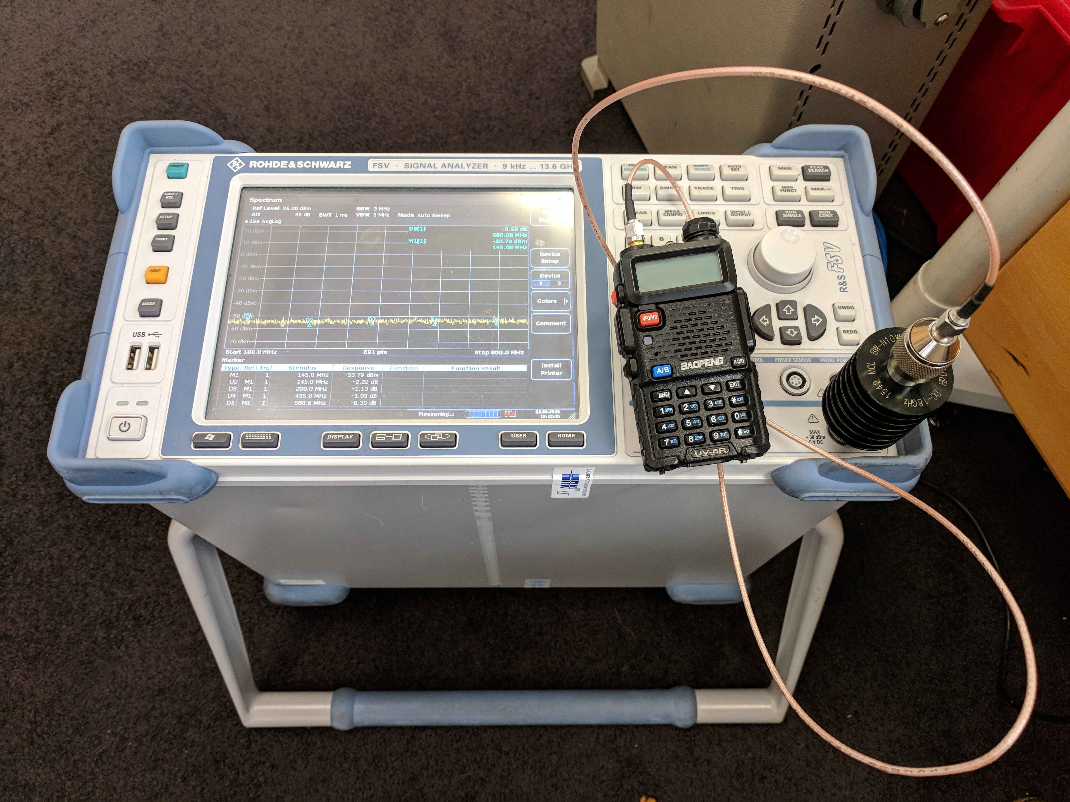
We're measuring conducted emissions, so lets cable a spectrum analyzer into the antenna socket. There's a 10dB pad too, just to protect the analyzer.
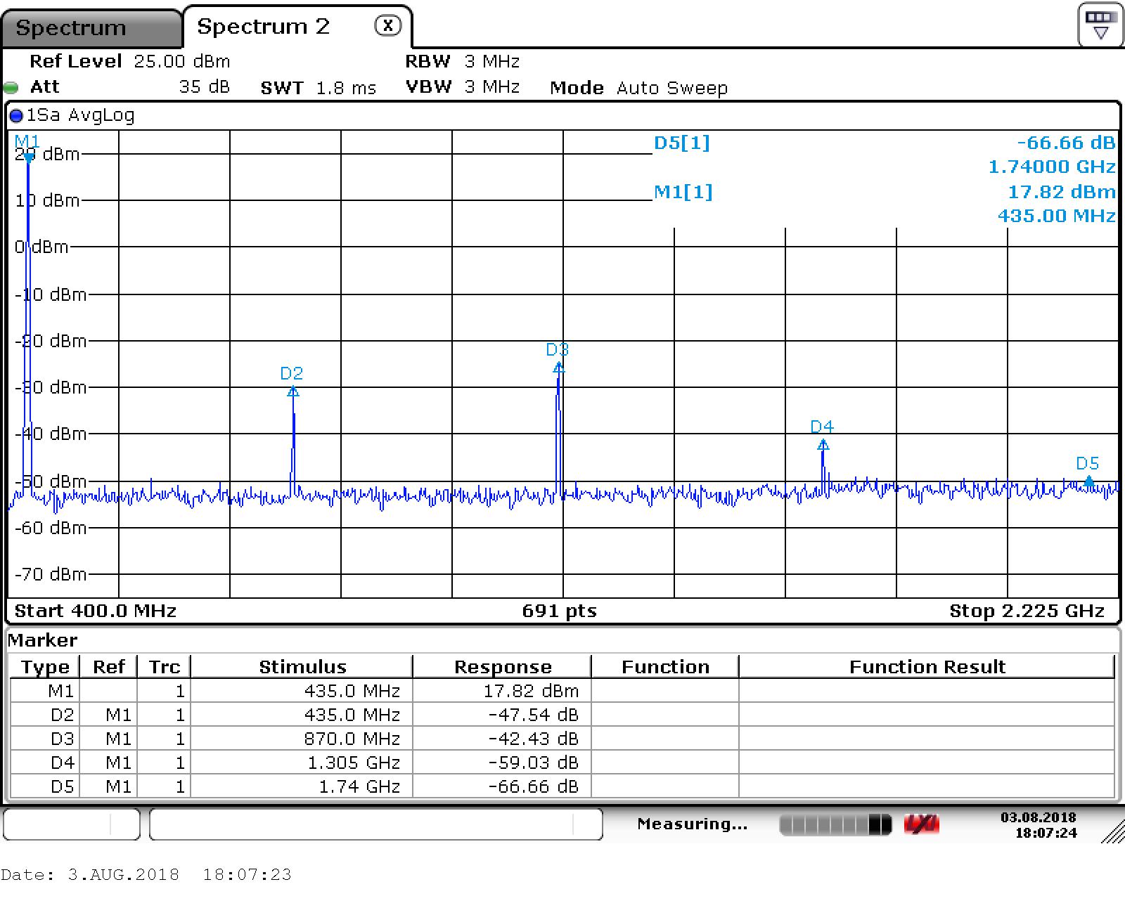
Putting a marker on the carrier, and delta markers on the harmonics it's easy to see their relative levels:
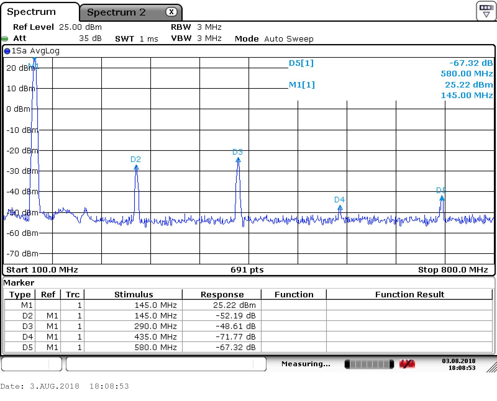
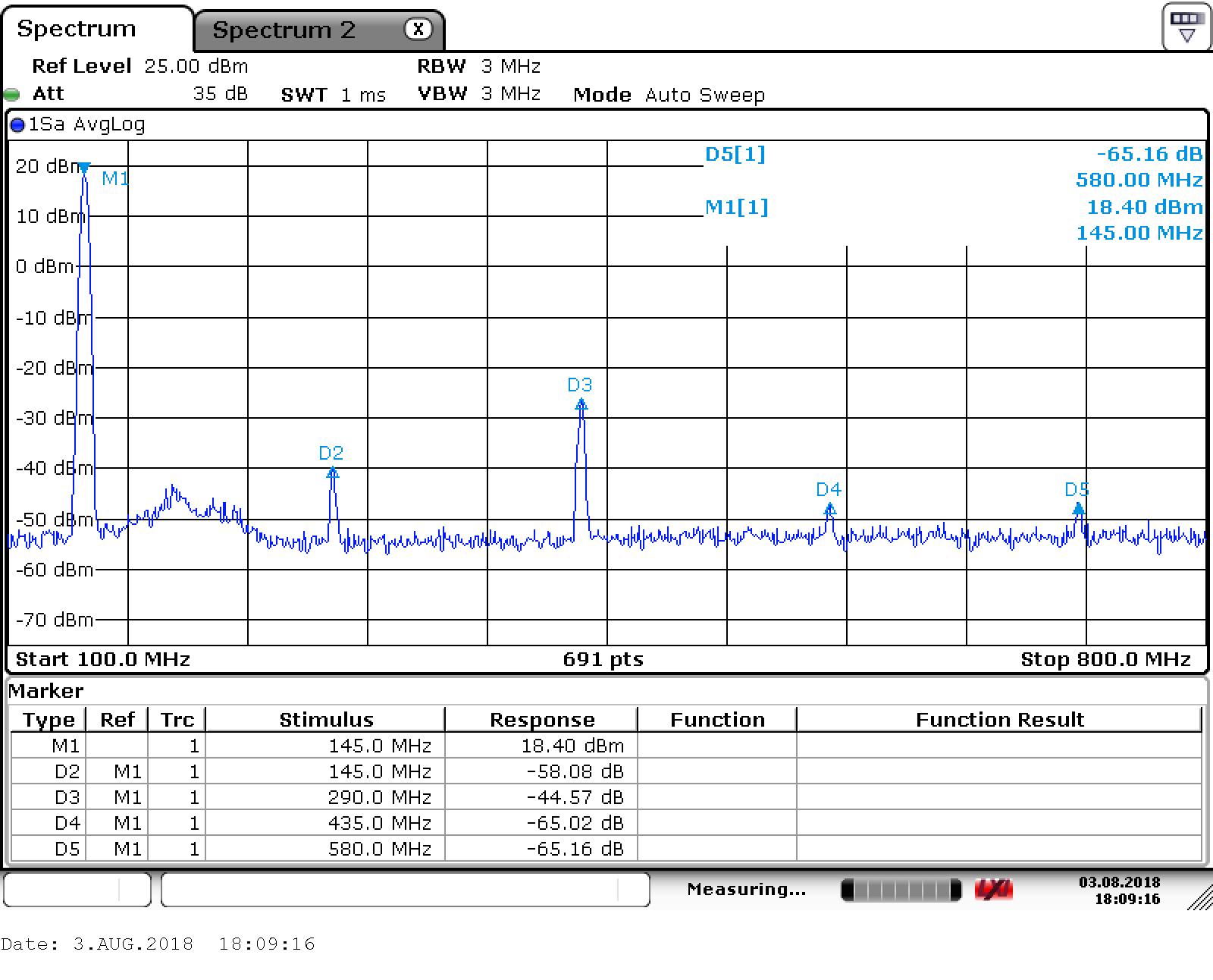
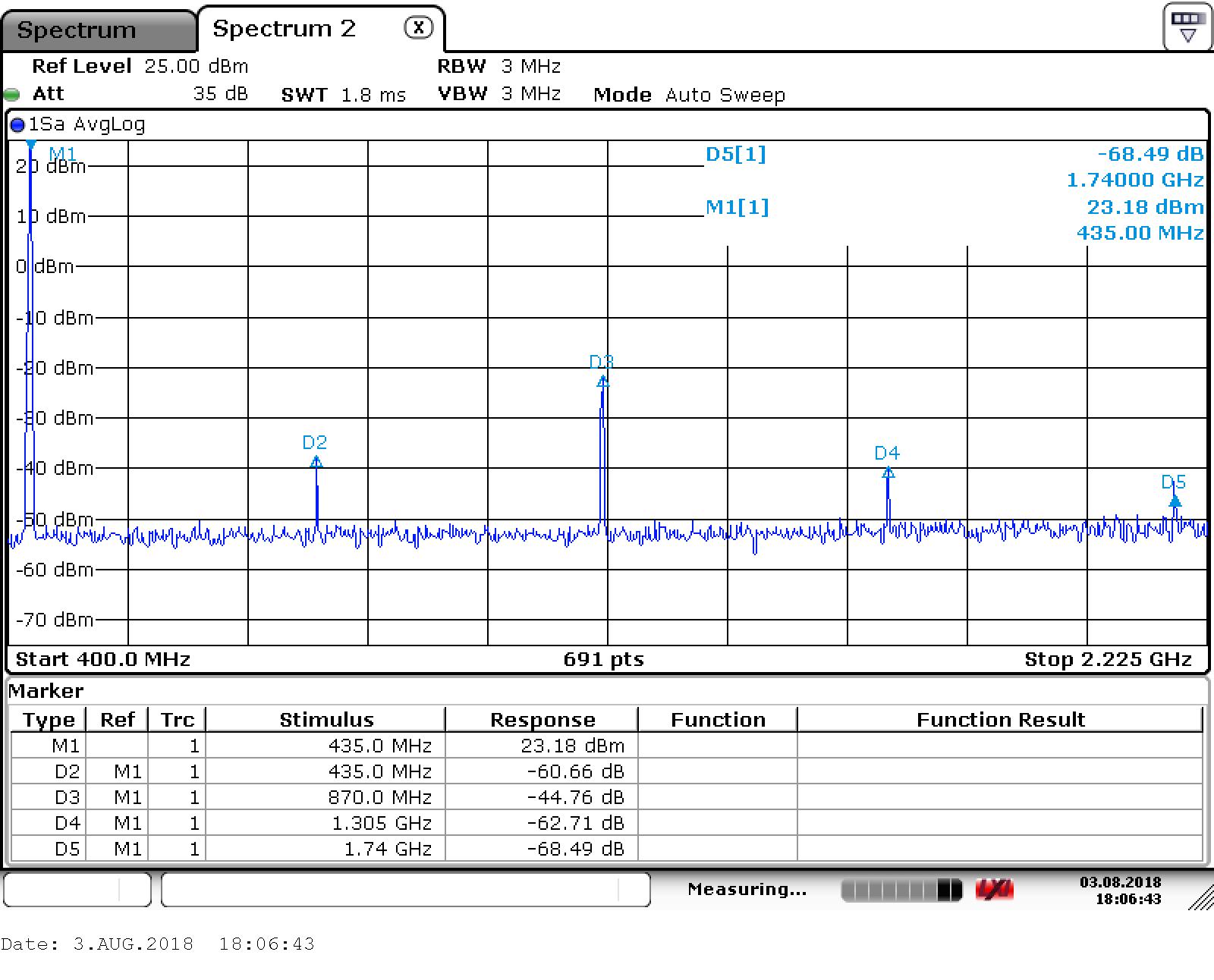
Summarizing, and adding 11dB to account for the 10dB attenuator, and cable loss, which I didn't measure:
| frequency_Hz | power | p1_dBm | d2_dBc | d3_dBc | d4_dBc | d5_dBc | |
|---|---|---|---|---|---|---|---|
| 0 | 145000000.0 | high | 36.22 | -52.19 | -48.61 | -71.77 | -67.32 |
| 1 | 145000000.0 | low | 29.40 | -58.08 | -44.57 | -65.02 | -65.16 |
| 2 | 435000000.0 | high | 34.18 | -60.66 | -44.76 | -62.71 | -68.49 |
| 3 | 435000000.0 | low | 28.82 | -47.54 | -42.43 | -59.03 | -66.66 |
None of the harmonics are above the FCC limit (-40dBc) which is a good start (ofcom's regulations on off-frequency emissions are not so helpfully precise).
Looking at the absolute powers of the harmonics, the worst is at -10.6dBm, and all of the third harmonics are greater than the FCC limit of -16dBm. Measurement uncertainty here is pretty large, but not enough to cover a fail by several dB.
| frequency_Hz | power | p1_dBm | p2_dBm | p3_dBm | p4_dBm | p5_dBm | |
|---|---|---|---|---|---|---|---|
| 0 | 145000000.0 | high | 36.22 | -15.97 | -12.39 | -35.55 | -31.10 |
| 1 | 145000000.0 | low | 29.40 | -28.68 | -15.17 | -35.62 | -35.76 |
| 2 | 435000000.0 | high | 34.18 | -26.48 | -10.58 | -28.53 | -34.31 |
| 3 | 435000000.0 | low | 28.82 | -18.72 | -13.61 | -30.21 | -37.84 |